The Elusive Concept of Group Delay
Group delay is a fundamental concept in the study of signal processing and wave propagation, providing crucial insights into how different frequency components of a signal are transmitted through a system. While often intuitively understood as the time it takes for a signal’s envelope to travel from one point to another, a deeper dive reveals a more nuanced reality. At its core, group delay quantifies the rate of change of the phase of a signal with respect to frequency. It is defined as the derivative of the phase response of a system with respect to angular frequency: $\tau_g = \frac{d\phi(\omega)}{d\omega}$, where $\tau_g$ is the group delay, $\phi(\omega)$ is the phase response, and $\omega$ is the angular frequency.
In a linear time-invariant (LTI) system, the ideal scenario is for all frequency components of a signal to be delayed by the same amount. This would result in a constant group delay across the entire frequency spectrum of interest. When the group delay is constant, the shape of the signal’s envelope is preserved during transmission, leading to faithful reproduction at the output. Think of sending a complex waveform, like a musical note, through a system. If the system introduces a constant group delay, all the constituent frequencies that make up that note will be shifted in time by the same duration, maintaining the note’s timbre and character.
However, real-world systems are rarely perfect. The phase response of a system is often not linear with frequency, leading to a non-constant group delay. This phenomenon is known as group delay distortion. When group delay varies with frequency, different frequency components of the signal’s envelope travel at different speeds. This can cause the envelope to spread out, distort, or even develop “ringing” artifacts. In audio systems, for example, significant group delay distortion can manifest as a muddy or unclear sound, particularly for transient signals like percussive sounds. In digital communication, it can lead to inter-symbol interference, where the tail of one symbol bleeds into the next, corrupting data. Understanding and mitigating group delay distortion is therefore a critical aspect of designing high-fidelity communication and signal processing systems.
In exploring the concept of group delay, particularly the intriguing phenomenon of negative group delay, you may find a related article that delves deeper into this subject. This article provides a comprehensive explanation of how negative group delay can occur in certain media and its implications in various applications, including telecommunications and signal processing. For more insights, you can read the article here: Understanding Negative Group Delay.
Unpacking the Nature of Group Delay

To truly grasp the implications of group delay, it’s essential to dissect its relationship with phase delay and understand the fundamental mathematical underpinnings. While often used interchangeably in casual discussion, phase delay and group delay represent distinct, albeit related, phenomena. Their interplay offers a richer understanding of signal transmission characteristics.
Phase Delay: The Journey of a Single Frequency
Phase delay, denoted as $\tau_p$, is a simpler concept. It represents the time it takes for a single frequency component of a signal to travel through a system. Mathematically, it is defined as the negative of the phase response divided by the angular frequency: $\tau_p(\omega) = -\frac{\phi(\omega)}{\omega}$. In an LTI system, if you inject a pure sine wave of a specific frequency, the phase delay tells you how much that sine wave’s phase has shifted when it emerges from the system, and when that shifted phase corresponds to the same point in its cycle as the original sine wave.
Consider a system with a phase response $\phi(\omega) = -k\omega$. Here, $k$ is a constant representing a fixed time delay. For any frequency $\omega$, the phase delay would be $\tau_p(\omega) = -\frac{-k\omega}{\omega} = k$. In this case, the phase delay is constant for all frequencies. This implies that each individual frequency component is delayed by the same amount of time, $k$. This ideal scenario is often the goal in signal transmission systems where preserving the integrity of individual frequency components is paramount.
The Interdependence of Phase and Group Delay
The relationship between phase delay and group delay becomes apparent when considering how the phase response changes with frequency. The group delay, as the derivative of the phase, is essentially measuring the rate of change of the phase. If the phase response is a straight line with respect to frequency (i.e., $\phi(\omega) = -k\omega$), then its derivative, the group delay, will be constant and equal to $k$. In this idealized case, phase delay and group delay are identical: $\tau_g(\omega) = \tau_p(\omega) = k$.
However, in most real-world systems, the phase response is not a perfect straight line. It often exhibits curvature. When the phase response is curved, the derivative (group delay) will vary with frequency, while the direct ratio (phase delay) will also vary, but in a different manner. For example, if a system has a phase response of $\phi(\omega) = -a\omega – b\omega^3$, where $a$ and $b$ are constants, the phase delay would be $\tau_p(\omega) = -\frac{-a\omega – b\omega^3}{\omega} = a + b\omega^2$. The group delay would be $\tau_g(\omega) = \frac{d}{d\omega}(-a\omega – b\omega^3) = -a – 3b\omega^2$.
Here, both phase and group delays are frequency-dependent, indicating distortion. The term $-a$ in both expressions represents the constant delay component, while the $b\omega^2$ and $3b\omega^2$ terms represent the frequency-dependent deviations. This deviation from a constant group delay is what causes the envelope of a complex signal to distort. The group delay is therefore a more direct measure of how the envelope of a signal is delayed, whereas the phase delay relates to the delay of the instantaneous phase of the carrier wave.
The Paradoxical Realm of Negative Group Delay
The concept of negative group delay often sparks intrigue and can seem counterintuitive at first glance. It challenges the common understanding that signals must travel forward in time. However, negative group delay does not imply a violation of causality or the ability to send information backward in time. Instead, it arises from specific system characteristics and can be understood by examining the phase response of the system.
Systems Exhibiting Negative Group Delay
Negative group delay is typically observed in systems that exhibit a rapidly increasing phase with frequency within a certain band. This can occur in passive or active systems with resonant structures or specific filter designs. For instance, certain types of resonant circuits, like coupled resonators or metamaterials, can be engineered to exhibit negative group delay over narrow frequency bands. In these scenarios, the phase response $\phi(\omega)$ decreases very steeply as $\omega$ increases within that band, such that its derivative $\frac{d\phi(\omega)}{d\omega}$ becomes negative.
Consider a system with a phase response that has a sharp “dip” or a steep negative slope within a specific frequency range. As you move along the frequency axis within this dip, the phase values become increasingly negative. The rate at which this phase becomes more negative with increasing frequency is precisely what the derivative captures. If this rate is large enough, the derivative becomes negative.
Causality and Negative Group Delay
It is crucial to reiterate that negative group delay in itself does not violate causality. Causality dictates that the output of a system cannot depend on future input values. Systems that exhibit negative group delay do not allow for the transmission of information faster than the speed of light or backward in time. The apparent “backward” propagation is an artifact of the measurement and the way the system interacts with the signal’s envelope, particularly around resonances or sharp phase transitions.
The signal’s energy, which is often associated with the envelope, is still propagating forward. However, the phase velocity (the speed at which a point of constant phase on a sinusoidal wave travels) can be faster than the speed of light, and in some engineered structures, even appear to be negative. But the group velocity (the speed at which the envelope of a wave packet travels) is what relates to the transmission of information and remains limited by the speed of light. Negative group delay occurs when the group velocity appears to be negative, but this is usually within a narrow frequency band where the interpretation of “envelope” becomes complex due to the rapid phase changes.
A useful analogy to understand this is to consider a carousel. If you are on the carousel and you look at the horses, their positions are constantly changing. If you focus on a specific horse, its movement might appear to be backward relative to your own rotation for a brief moment. However, the carousel as a whole is still rotating forward. Similarly, in a system with negative group delay, individual frequency components might exhibit phase behavior that, when combined to form an envelope, appears to lead to a negative delay. But the overall flow of information is still causal. The negative group delay is an emergent property of the system’s interaction with the signal’s frequency spectrum, not an indication of information traveling backward in time.
Manifestations and Implications of Group Delay Distortion
The consequences of non-constant group delay, or group delay distortion, are far-reaching and can significantly impact the performance of various signal processing and communication systems. Understanding these implications is key to designing robust and reliable technologies.
Impact on Signal Integrity
The primary effect of group delay distortion is the alteration of the signal’s shape. When different frequency components of a signal’s envelope are delayed by different amounts, the envelope can spread, become distorted, or even develop unwanted oscillations. This can lead to a degradation of signal quality, making it harder for the receiving system to correctly interpret the transmitted information.
In analog systems, such as audio or video transmission, group delay distortion can lead to audible or visible artifacts. For audio signals, it can cause a loss of transient clarity, making percussive sounds sound smeared or indistinct. High frequencies might arrive at different times than low frequencies, leading to a loss of crispness and detail. In video, it can result in color fringing or motion blur, especially at edges and during rapid scene changes.
In digital communication systems, group delay distortion is a major source of inter-symbol interference (ISI). When the delay of different frequency components within a symbol varies, the symbol’s energy spreads out in time, interfering with adjacent symbols. This can lead to bit errors, requiring retransmissions and reducing the overall data throughput. For high-speed communication systems, even small amounts of group delay distortion can render the system inoperable without appropriate compensation.
Applications Where Group Delay is Critical
Despite the challenges, there are also applications where controlling and even manipulating group delay is crucial. Precision timing is paramount in many scientific and engineering domains.
High-Speed Data Communication: In optical fiber communication, for example, the dispersion (which is directly related to group delay distortion) in the fiber can limit the achievable data rates and transmission distances. Advanced techniques are employed to either minimize dispersion or actively compensate for it.
Radar and Sonar Systems: These systems rely on the precise timing of transmitted and received pulses to determine distance and velocity. Group delay characteristics of the transmission medium and the processing electronics are critical for accurate measurements.
Medical Imaging: Techniques like Magnetic Resonance Imaging (MRI) rely on complex radio frequency pulses and their precise timing and shaping. Group delay distortion in the RF chain can affect image quality and diagnostic accuracy.
Metamaterials and Advanced Optics: As mentioned earlier, engineered structures like metamaterials can be designed to exhibit specific group delay characteristics, including negative group delay. These materials hold promise for novel applications in cloaking, super-resolution imaging, and advanced optical devices where precise control over wave propagation is required. By carefully designing the constituent elements and their arrangement, researchers can sculpt the group delay response to achieve desired wave manipulation effects.
In the exploration of group delay, the concept of negative group delay has garnered significant attention due to its intriguing implications in various fields such as telecommunications and signal processing. For a deeper understanding of this phenomenon, you can refer to a related article that delves into the intricacies of negative group delay and its applications. This informative piece can be found at this link, where you will discover how negative group delay challenges conventional notions of signal transmission and offers potential advancements in technology.
Measurement and Mitigation Strategies
| Metric | Description | Typical Values | Relevance to Negative Group Delay |
|---|---|---|---|
| Group Delay (τg) | Derivative of the phase response with respect to angular frequency (dφ/dω) | Can be positive or negative (e.g., -10 ns to +50 ns) | Negative values indicate signal components appear to exit a system before entering, a key feature of negative group delay |
| Phase Response (φ) | Phase shift introduced by the system as a function of frequency | Varies from -π to π radians | Rapid phase changes with frequency can cause negative group delay |
| Frequency Range | Range over which negative group delay is observed | Depends on system; often narrowband (e.g., 1 MHz to 1.1 MHz) | Negative group delay typically occurs in specific frequency bands |
| Signal Distortion | Degree to which the output signal shape is altered | Low to moderate distortion preferred | Excessive distortion can invalidate the interpretation of negative group delay |
| Energy Gain | Ratio of output to input signal amplitude | Often greater than 1 in negative group delay circuits | Apparent “advancement” of signal is often accompanied by gain |
| System Type | Physical or electronic system exhibiting negative group delay | Examples: electronic circuits, metamaterials, optical fibers | Determines practical implementation and applications |
Understanding how to measure group delay and implement strategies to mitigate its distortion is essential for practical applications. Various techniques and technologies have been developed to address these challenges.
Techniques for Measuring Group Delay
Measuring group delay typically involves analyzing the phase response of a system over a range of frequencies. Several methods are commonly employed:
Frequency Domain Analysis: This is the most direct approach. A network analyzer or a spectrum analyzer can be used to measure the system’s scattering parameters (S-parameters), from which the phase response can be extracted. By numerically differentiating the phase response with respect to frequency, the group delay can be calculated. This method provides a detailed frequency-by-frequency breakdown of the group delay.
Time Domain Analysis (Impulse Response): If the system’s impulse response is known or can be measured, the group delay can be computed by taking the Fourier transform of the impulse response to obtain its frequency response, and then proceeding as in the frequency domain analysis. Alternatively, by observing the delay of the envelope of a short pulse passing through the system, an estimate of the group delay can be obtained. However, this method is less precise for detailed group delay characterization.
Chirp Signal Analysis: Transmitting a linear frequency-modulated (chirp) signal through the system and analyzing the frequency-dependent arrival times of different parts of the chirp pulse is another effective method. The chirp signal has a continuously varying frequency, allowing for a sweeping measurement of the group delay across a wide bandwidth.
Interferometric Methods: For very precise measurements, especially in optical systems, interferometric techniques can be used to measure the phase accumulation as a function of frequency with high accuracy.
Strategies for Group Delay Compensation
Once group delay distortion is identified and quantified, various strategies can be employed to compensate for it:
Equalization: This is a widely used technique where an electronic circuit or digital algorithm is used to introduce an inverse group delay response. An equalizer essentially aims to “undo” the distortion introduced by the main system. For example, in audio, graphic equalizers can adjust the level of different frequency bands, indirectly affecting the perceived group delay. In digital systems, digital filters are designed to introduce an opposite group delay characteristic.
Dispersion Compensation Fibers: In optical communications, specialized optical fibers with carefully engineered dispersion characteristics are used to counteract the dispersion introduced by standard transmission fibers. These fibers effectively introduce an opposite group delay to that of the main fiber path.
Pre-distortion: In some cases, the signal can be pre-distorted before transmission to anticipate and cancel out the expected group delay distortion of the channel. This requires a good understanding of the channel’s characteristics.
System Design Optimization: For new system designs, careful selection of components and architectures can minimize inherent group delay distortion. This might involve choosing low-distortion amplifiers, filters with flatter phase responses, or utilizing specific circuit topologies. For example, in filter design, Butterworth or Chebyshev filters often have more linear phase responses over their passband compared to other filter types, albeit with trade-offs in other performance metrics.
The Nuances of Negative Group Delay in Practical Systems
While negative group delay might sound like a theoretical curiosity, it has tangible implications and applications in specialized areas. Understanding how it arises and is practically observed is key to leveraging its potential.
Engineered Systems and Metamaterials
As previously discussed, negative group delay is often a characteristic of engineered systems, particularly those employing resonant structures or metamaterials. These materials are artificially structured at sub-wavelength scales to exhibit electromagnetic or acoustic properties not found in natural materials. By precisely designing the geometry and arrangement of these structures, engineers can create systems with specific phase responses that lead to negative group delay over certain frequency bands.
For instance, a series of coupled resonant cavities can exhibit a sharp decrease in phase with increasing frequency, leading to a negative derivative and thus a negative group delay. Similarly, specific arrangements of metallic or dielectric elements in metamaterials can create unique electromagnetic responses, including negative group delay, that can be used for applications like wave manipulation and subwavelength imaging.
Causality-Preserving Interpretations
It is vital to reiterate that the negative group delay observed in these systems does not imply a violation of causality. The interpretation of “delay” here refers to the transit time of the envelope of a wave packet. In a system exhibiting negative group delay, the phase velocity might be greater than the speed of light, or even appear to be negative. However, the group velocity, which represents the speed of energy and information transfer, remains causal.
The phenomenon can be understood by considering the energy flow within the system. Even though the phase of individual frequency components might be rapidly changing in a way that suggests a negative delay, the overall energy pulse is still propagating forward in time, albeit with some peculiar phase interactions. The negative group delay is a manifestation of the system’s complex interaction with the signal’s spectral components, particularly at or near resonance frequencies where the phase changes rapidly.
Potential Applications and Research Frontiers
The ability to engineer negative group delay opens up exciting possibilities for novel applications and research:
Pulse Compression and Expansion: Negative group delay can be exploited to compress or expand signal pulses. By carefully designing a system with a specific negative group delay characteristic, a short pulse can be compressed, or a broad pulse can be expanded, which can be useful in various signal processing tasks.
Superluminal Phenomena in a Causal Framework: While not allowing for superluminal information transfer, negative group delay allows for the observation of “superluminal” phenomena in a causal framework. This can lead to a deeper understanding of wave propagation and causality itself.
Advanced Optical Devices: In optics, negative group delay could be used in novel device designs for manipulating light pulses, creating specialized delay lines, or developing new types of optical switches.
Resonant Wave Amplification: In some active systems, negative group delay can be associated with resonant amplification, where the signal’s amplitude increases as it propagates through the device.
The study of negative group delay continues to be an active area of research, pushing the boundaries of our understanding of wave phenomena and leading to the development of innovative technologies. It highlights the intricate relationship between phase, frequency, and time in signal transmission, reminding us that even seemingly counterintuitive concepts can have profound practical implications when understood within the correct theoretical framework.
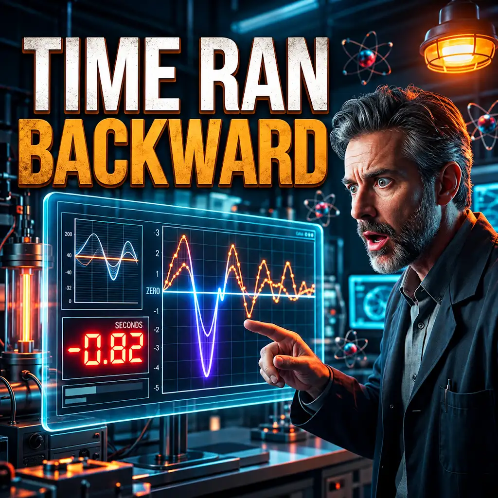
Physicists Just Measured a Negative Second.
FAQs
What is group delay in signal processing?
Group delay is a measure of the time delay experienced by different frequencies within a signal as they pass through a system. It indicates how a system affects the phase relationship of the various frequency components of the signal.
How is group delay typically represented?
Group delay is often represented as a function of frequency. It shows how the phase response of a system changes with frequency, providing valuable information about the system’s behavior.
What does it mean when group delay is negative?
When group delay is negative, it indicates that higher frequency components of the signal are arriving earlier than lower frequency components. This can lead to distortion in the signal and affect the overall performance of the system.
What are some common causes of negative group delay?
Negative group delay can be caused by various factors such as phase distortion, non-linear phase response, or certain types of filters that introduce this phenomenon. It is important to identify and address these causes to ensure the integrity of the signal.
How can negative group delay be mitigated or corrected?
To mitigate or correct negative group delay, techniques such as equalization, phase compensation, or using different types of filters with improved phase characteristics can be employed. These methods help to restore the proper phase relationships within the signal and minimize the impact of negative group delay.